|
This is the web edition of the original ⮫ AC500-S safety user manual, version 1.3.2. This web edition is provided for quick reference only. The original safety user manual must be used to meet functional safety application requirements. |
The input modules can be plugged only on spring-type TU582-S I/O terminal unit. The unique mechanical coding on I/O terminal units prevents a potential mistake of placing the non-safety I/O module on safety I/O terminal unit and the other way around. Basic information on system assembly is shown here.
⮫ «Planificación e instalación mecánicas»
Installation and maintenance have to be performed according to the technical rules, codes and relevant standards, e.g., EN 60204 part 1, by skilled electricians only.
Assembly of DI581-S

PELIGRO
Hot plug and hot swap of energized modules is not permitted. All power sources (supply and process voltages) must be switched off while working with safety modules.
-
Fig. 416: Assembly instructions 
Put the module on the terminal unit.
The module clicks in.
-
Then press the module with a force of at least 100 N into the terminal unit to achieve proper electrical contact.
Disassembly of DI581-S
-
Fig. 417: Disassembly instructions 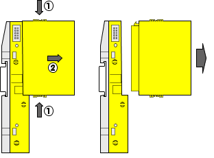
Press above and below, then remove the module.
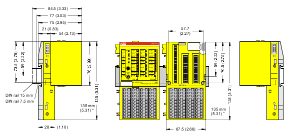
Dimensions
Electrical connection

AVISO
The same TU582-S is used by all AC500-S safety I/O modules. If TU582-S is wired for DX581-S module with safety digital outputs and DI581-S or AI581-S modules are occasionally placed on this terminal unit, under no circumstances it is possible that safety digital output clamps on TU582-S become energized due to a wrongly placed DI581-S or AI581-S safety I/O modules.
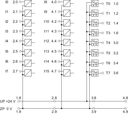
The electrical connection of the I/O channels is carried out using 40 terminals of the I/O terminal unit. I/O modules can be replaced without re-wiring the terminal units.
The terminals 1.8, 2.8, 3.8 and 4.8 as well as 1.9, 2.9, 3.9 and 4.9 are electrically interconnected within the I/O terminal unit and have always the same assignment, independent of the inserted module:
-
Terminals 1.8, 2.8, 3.8 and 4.8: Process voltage UP = +24 V DC
-
Terminals 1.9, 2.9, 3.9 and 4.9: Process voltage ZP = 0 V
The assignment of other terminals:
|
Terminals |
Signal |
Meaning |
|---|---|---|
|
1.0, 1.2, 1.4, 1.6, 3.0, 3.2, 3.4, 3.6 |
T0, T1, T2, T3, T4, T5, T6, T7 |
Connectors of 8 test pulse outputs T0, T1, T2, T3, T4, T5, T6, T7 |
|
2.0 ... 2.7, 4.0 ... 4.7 |
I0, I1, I2, I3, I4, I5, I6, I7, I8, I9, I10, I11, I12, I13, I14, I15 |
16 safety digital inputs |
|
1.8, 2.8, 3.8, 4.8 |
UP |
Process power supply +24 V DC |
|
1.9, 2.9, 3.9, 4.9 |
ZP |
Central process earth |
|
1.1, 1.3, 1.5, 1.7, 3.1, 3.3, 3.5, 3.7 |
Free |
Not used |
AVISO
The process voltage must be included in the earthing concept of the control system (e.g., earthing the minus pole).
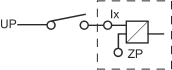
Examples of connections
Examples of electrical connections with DI581-S module and single channel Ix.